Table of Contents
V1 AIO box
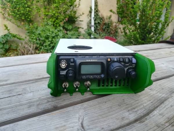
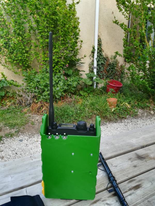
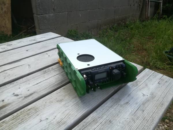
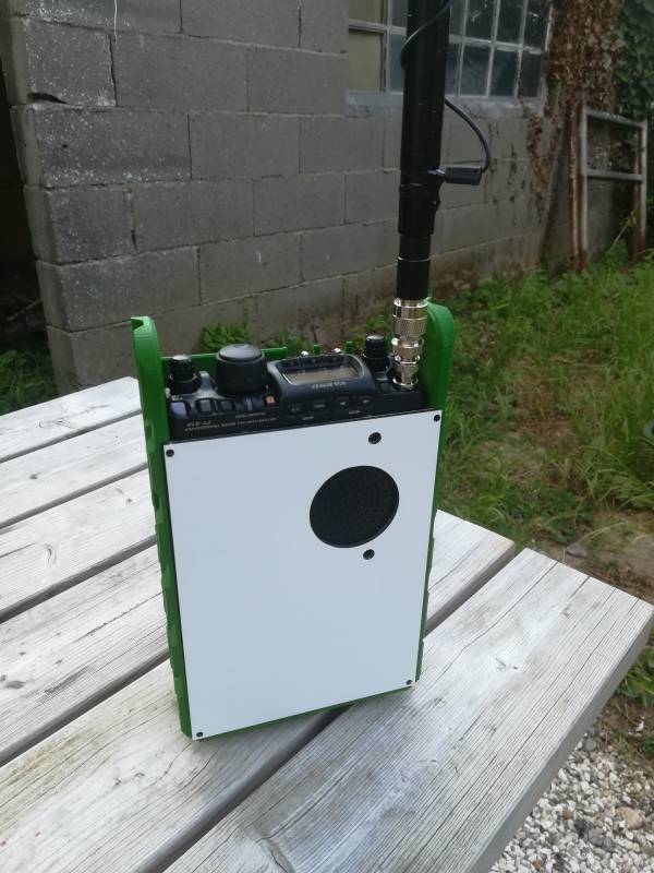
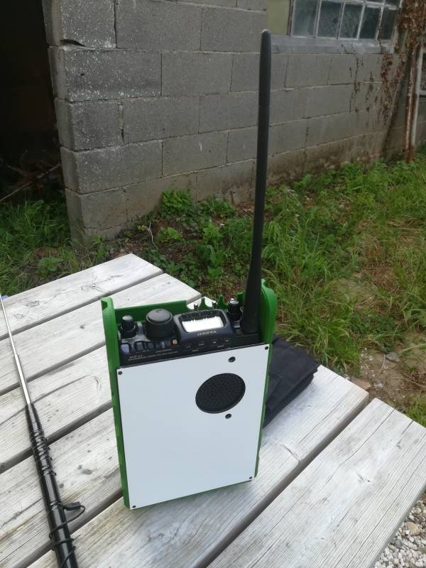
This is the first version of the project. The main part is the case, and there is just a top plate to be CNC milled with 3mm Dibond sheet to close it.
It's quite a huge part, the sizes are 155.3×251.5x70mm and the total weight is about 330g printed.
I've printed it with standard PLA, but the green of Dailyfil is quite good and give it a better military feeling, even it's not the right OTAN green.
This version weight is 2150g all included (3d printed parts, CNC milled parts, FT-818 with its internal battery pack, the 3S2P lithium 18650 battery pack, RPI, connectors, etc).
List of components
| Designation | Qty | Link | Notes |
|---|---|---|---|
| DC socket 5.5mm x 2.1mm | 1 | link | used as the charging port for the battery pack |
| Lithium cells 18650 3300mah | 6 | link | to make a 6600mah 12.6V battery pack |
| BMS lithium 3S | 1 | link | to balance and protect the battery pack |
| XT60 socket with screw mount | 2 | link | one for external power for FT-818 and second one for the RPI4 |
| Lithium charger 2A | 2 | link | to charge the battery pack |
| Good quality lever switches | 3 | link | To select power supplies or battery, see below explanations |
| SO239 connector with base plate | 1 | link | |
| 40x40mm fan protection + filter | 2 | link | |
| 40x40mm fan 12V | 2 | link | |
| Thermal switch 55°C NO | 1 | link | to switch on fans when temperature is reaching a limit |
| 12V to 5V step down + USB | 1 | link | To power the RPI4 and eventually to recharge your smartphone device |
| RJ45 socket | 1 | link | To directly connect to the RPI through RJ45 |
| 4mm banana socket | 1 | link | for counterpoise connection |
I don't speak here about small parts like M3 screws, nuts, nickel plates for the battery pack, wires, etc etc.
Switches
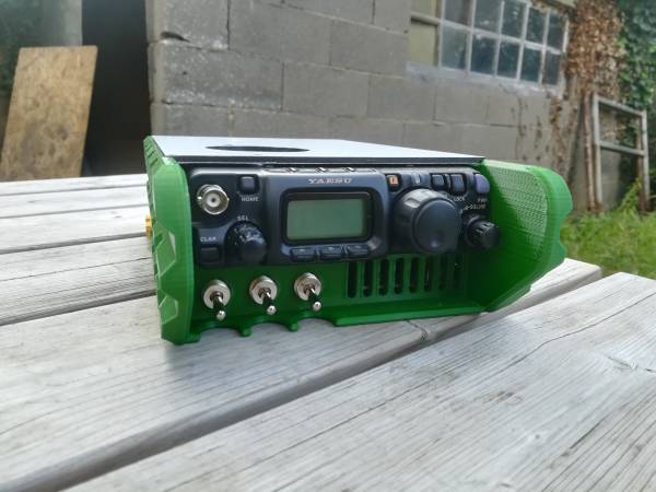
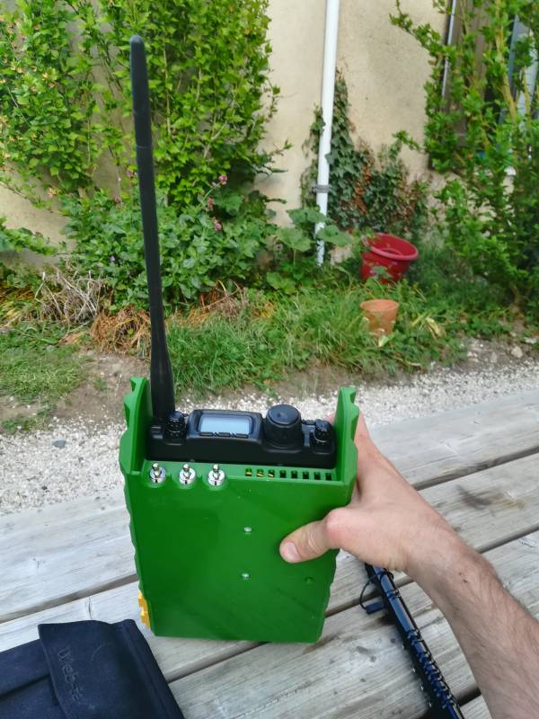
I've decided on this version to integrate 3 lever switches on the front :
We'll call them from left to right SW1, SW2 and SW3.
SW1 is finally a switch for the internal battery pack of the FT-818. I've noticed with my USB soundcard that it's still draining some current from the FT-818, even the rig is off and the RPI is off too. So the idea, as we want to have everything plugged for ever, is to switch off the internal battery pack to avoid current draining and discharging the battery pack.
Don't forget to switch it on when you want to recharge this internal battery !
SW2 will switch on the 6600mah battery pack, which is connected to the radio with the Yaesu supplied jack connector. I'll act as an external PSU for the radio.
SW3 will switch on the RPI4 (in fact the 12V 5V step down to power it on or off. Also, SW3 is used for the 12V fans through the thermal switch.
Thermal switch
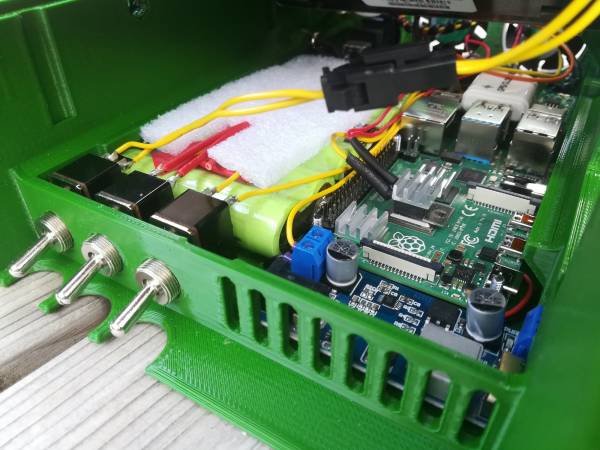
At the beginning, I've used a 40°C NO thermal swith you can see there, glued to the main chip of the RPI4 :
I've also added a small heatsink on the top, just to help a bit.
But 40°C seems to be too low, the fans are switched on maybe more than 90% of time, so I've ordered a 55°C version to have the fans switching a bit less (Need to be tested as of 26/04/2020).
The idea is to force the cooling of the RPI only when needed, to avoid having the noise of fans all the time, and to reduce the current draw on the battery pack.
External connectors
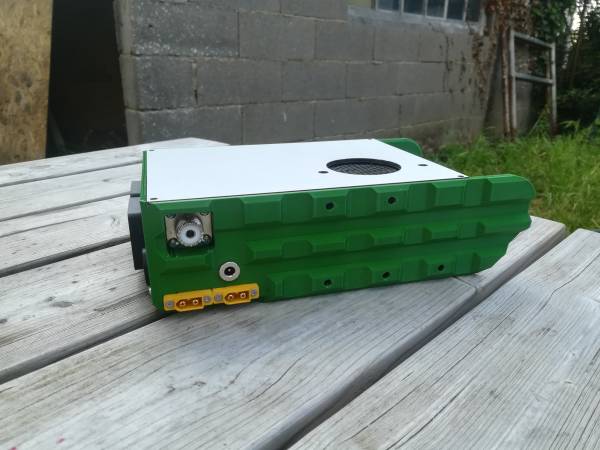
Some connectors have been added on the case, fully integrated. Let's take a look on the left side :
They are there 2x XT60 connectors, a SO239 panel mount socket and a DC plug.
The XT60 connectors are for external power for the box. The one on the left is directly connected to the FT-818 with the jack connector at the rear of the rig. It's wired in parallel with the battery pack and is designed to be plugged to an external 13.8V PSU. It'll also be used to recharge the internal battery pack.
The XT60 connector on the right is for the RPI4. It's directly connected to the step down board, so once you plug a PSU on it, the RPI4 will start.
At the moment of this early version, those connectors are not protected. You'll have to use them only when SW2 and SW3 are switched off, or the battery pack will be connected to the PSU and will be damaged !
The DC connector is only for charging the battery pack with a suitable charger (see the components list for example). It's direclty connected to BMS of the battery pack, so you don't need to switch on SW2 to charge it.
The SO239 connector is just an extension of the rear HF connector on the radio. On this version is very close to the box and you can't fit a PL259 with screw system :
I need to salvage a connector, to unmount the screw, remove the shield in order to solder it. OK, it's unshielded, but on about 30mm, after some tests, that seems to be fine.
OK, now, let's take a look to the rear side :
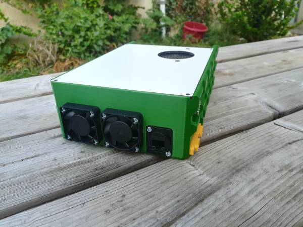
There are the 2 fans, and the RJ45 panel mount connector. I've been thinking a bit if it's a good idea or not. As I use my RPI4 with VNC viewer, I can connect through my smartphone, a tablet, a computer directly by wifi. Just to be precise, I didn't configure a hotspot inside the RPI, I create a hotspot on my smartphone and here we are, everything is in fact connected to my smartphone.
BUT, what if there is some wifi interferences or other problems ? That's why I've added this connector. I've configured a fixed IPV4 address on the RPI, so I can connect a computer, configured the same way, with a fixed address.
Just in case…
The right side :
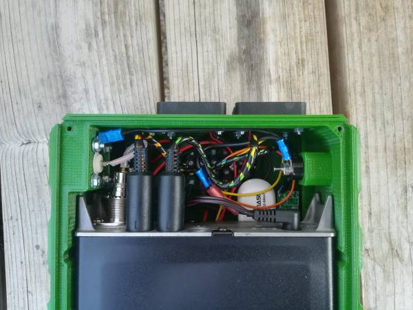
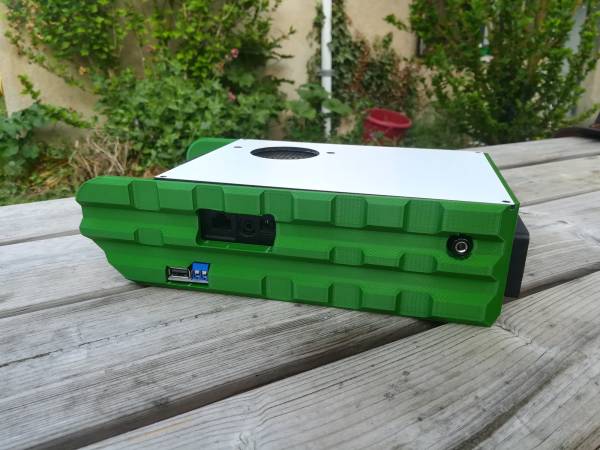
On this side, you've got a hole for the mic, headphone connector of the FT-818 and you've got a banana plug. This connector is directly connected to the body of the FT-818 by the ground screw and is designed to connect a ground wire, counterpoise, etc.
Now you just need to have your counterpoises wires with a banana connector. Very easy to plug and unplug, and resistant, quite big contacts.
Last but not least, the step down board comes with a USB plug to connect for example your smartphone in order to recharge it. pretty neat if you've running low on battery. That way you don't need to carry an extra power bank.
Accessories port
There are 5 holes with insert for M5 nuts on the left side. The idea is to have the hability to add so extra components on the box, and firmly attach them for on field operation.
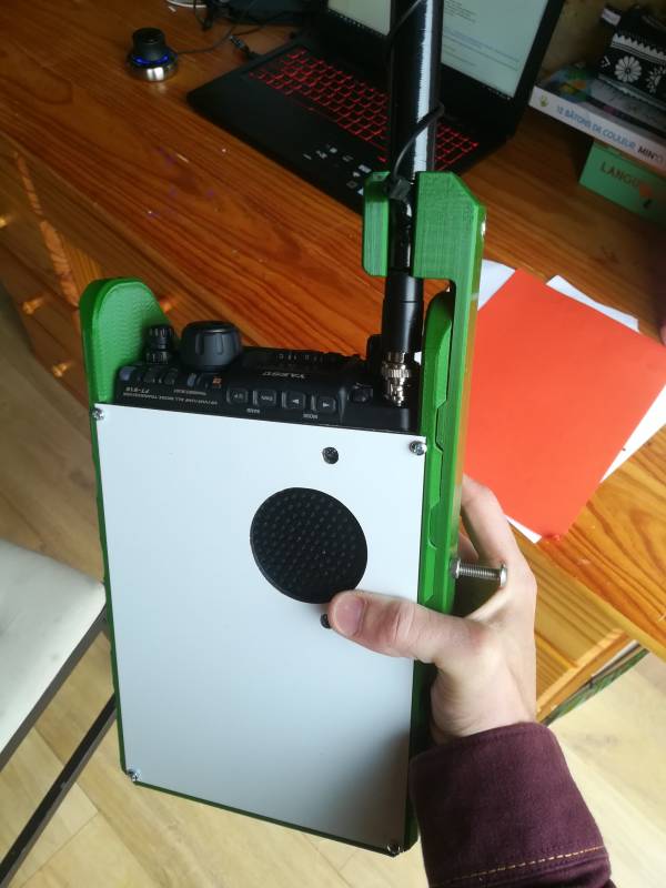
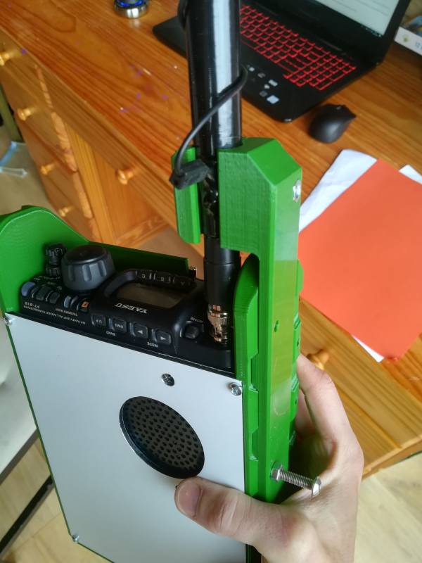
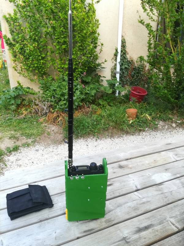
The first example is this jaw to maintain an MFJ1899T antenna (also know as ATX Walkabout 2) on the BNC connector :
I've always thought that this kind of whip antenna is very dangerous for the BNC connector. If you shock it, you can damage a lot your radio, even more true when you are on field operations.
So that way, it's firmly maintened to avoid that, and why not use it as a manpack mobile station.
I know there are other antennas like that, and the design could be adjusted for other types of antennas too.
Files
You can download the global archive here : files_v1.zip
Please don't forget that it's still a prototype, V1 version. I tried to solve any issues I've seen on building it, but it's still a bit tricky to build it.

