This is an old revision of the document!
Table of Contents
V1 AIO box
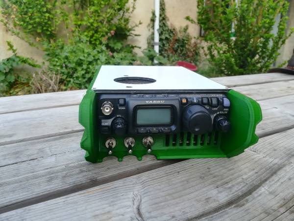
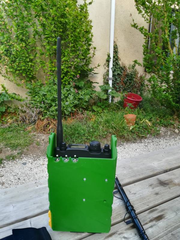
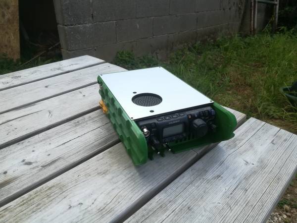
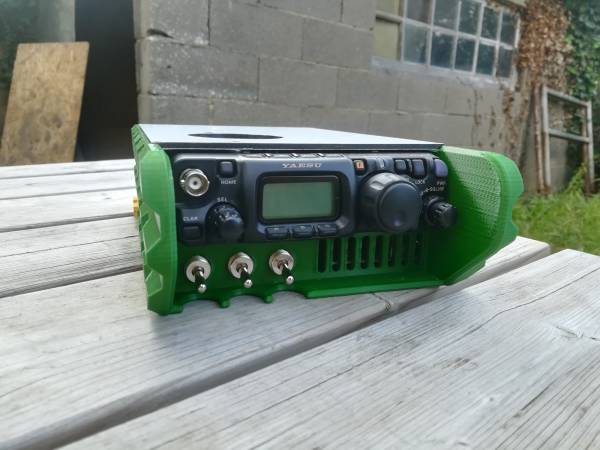
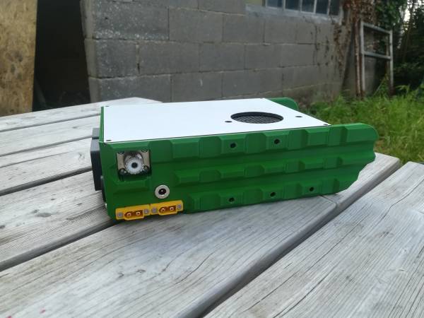
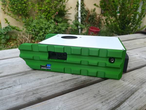
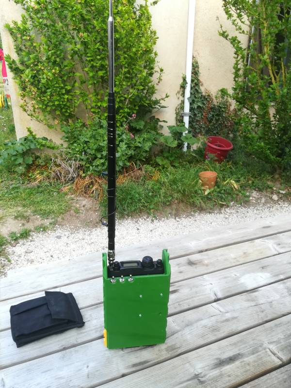
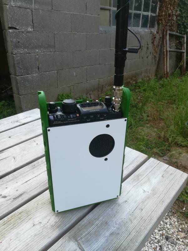
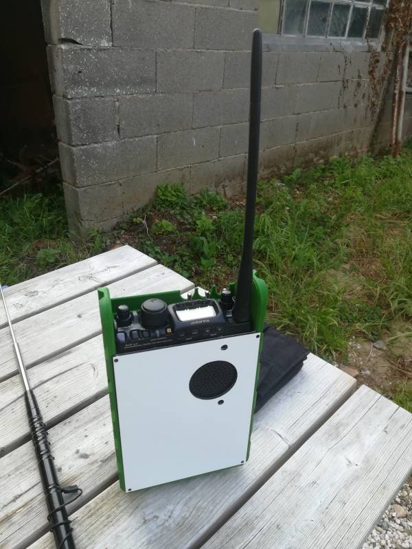
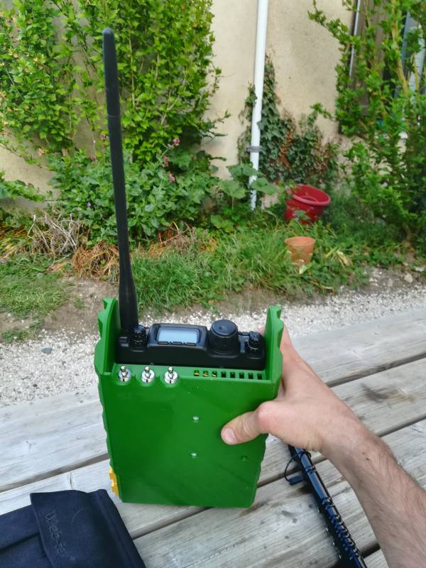
This is the first version of the project. The main part is the case, and there is just a top plate to be CNC milled with 3mm Dibond sheet to close it.
It's quite a huge part, the sizes are 155.3×251.5x70mm and the total weight is about 330g printed.
I've printed it with standard PLA, but the green of Dailyfil is quite good and give it a better military feeling, even it's not the right OTAN green.
List of components
| Designation | Qty | Link | Notes |
|---|---|---|---|
| DC socket 5.5mm x 2.1mm | 1 | link | used as the charging port for the battery pack |
| Lithium cells 18650 3300mah | 6 | link | to make a 6600mah 12.6V battery pack |
| BMS lithium 3S | 1 | link | to balance and protect the battery pack |
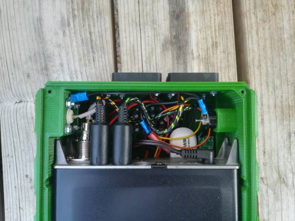
| XT60 socket with screw mount | 2 | link | one for external power for FT-818 and second one for the RPI4 |
| Lithium charger 2A | 2 | link | to charge the battery pack |
| Lever good quality switches | 3 | link | To select power supplies or battery, see below explanations |
| SO239 connector with base plate | 1 | link | |
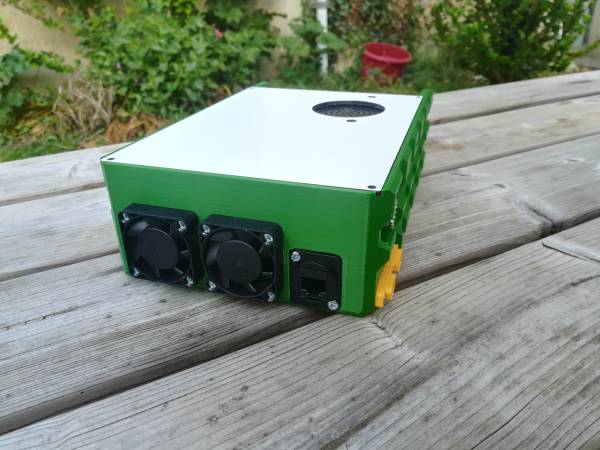
| 40x40mm fan protection + filter | 2 | link | |
| 40x40mm fan 12V | 2 | link | |
| Thermal switch 55°C NO | 1 | link | to switch on fans when temperature is reaching a limit |
| 12V to 5V step down + USB | 1 | link | To power the RPI4 and eventually to recharge your smartphone device |
| RJ45 socket | 1 | link | To directly connect to the RPI through RJ45 |
I don't speak here about small parts like M3 screws, nuts, nickel plates for the battery pack, wires, etc etc.
Switches
I've decided on this version to integrate 3 lever switches on the front :
We'll call them from left to right SW1, SW2 and SW3.
SW1 is finally a switch for the internal battery pack of the FT-818. I've noticed with my USB soundcard that it's still draining some current from the FT-818, even the rig is off and the RPI is off too. So the idea, as we want to have everything plugged for ever, is to switch off the internal battery pack to avoid current draining and discharging the battery pack.
Don't forget to switch it on when you want to recharge this internal battery !
SW2 will switch on the 6600mah battery pack, which is connected to the radio with the Yaesu supplied jack connector. I'll act as an external PSU for the radio.
SW3 will switch on the RPI4 (in fact the 12V 5V step down to power it on or off. Also, SW3 is used for the 12V fans through the thermal switch.
Thermal switch
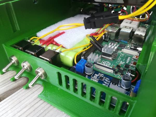
At the beginning, I've used a 40°C NO thermal swith you can see there, glued to the main chip of the RPI4 :
I've also added a small heatsink on the top, just to help a bit.
But 40°C seems to be too low, the fans are switched on maybe more than 90% of time, so I've ordered a 55°C version to have the fans switching a bit less (Need to be tested as of 26/04/2020).
The idea is to force the cooling of the RPI only when needed, to avoid having the noise of fans all the time, and to reduce the current draw on the battery pack.

