ft818:aio_box:v2
This is an old revision of the document!
Table of Contents
V2 AIO Box
Changelog
- Box has now some rear legs to permit to do not install it vertically on the fans.
- The bottom has been replaced by a CNC milled aluminium plate, which acts as a heatsink for the Pi4, which is now upside down, with thermal contact of the chip to the aluminium plate, by the mean of an aluminium block.
- The DC connectors area on the left is now with an aluminium plate, which permits to adapt only the plate to different types of connectors (in standard XT60, but can be adapted to Anderson Powerpole as well or others).
- External DC connectors are reduced to only one connector, which acts as a DC in PSU, charging port for battery back → an internal lithium charging board is now installed inside the box, so there is no need to have another charger for the lithium, just a 13.8V to 16V DC input can charge the lithium battery pack.
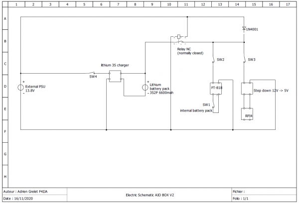
- New wiring diagram for the setup, which is simpler.
- USB GPS dongle has been tested to work well on V1, even it's installed inside the box. The signal is still well received by the dongle, so it's not planned to change.
- Better hole for disconnecting the microphone plug, to be able to put the thumb to release.
Wiring diagram
electric_schematic_aio_box_v2.pdf
This diagram is a lot more simpler than the V1 version (for which I didn't make one).
There is the need to add a relay to cut the battery pack if there is an external power supply connected, to prevent damaging the battery pack.
Also, a new switch is added, SW4 to activate the charging process with the internal lithium charger.
That way, the SW2 and SW3 are not sources of errors, if they are on either the PSU is connected (to avoid injecting DC in the battery pack).
ft818/aio_box/v2.1588512407.txt.gz · Last modified: 2020/05/03 15:26 by f4ija


